Saturday 6 December 2014

SSLVPN on an ASA

Here we go, the last piece of the VPN puzzle.


How do we configure an SSLVPN on a Cisco ASA.

We're going to do this all from the CLI but it is extremely easy to do via the ASDM wizard.

I've simply configured a Windows 7 box to point directly at the inside interface of the ASA, and allow a VPN to be configured there.
For reference, the inside interface IP is 10.0.0.1 and the Windows 7 box is 10.0.0.20.

Lets lay out a few requirements:


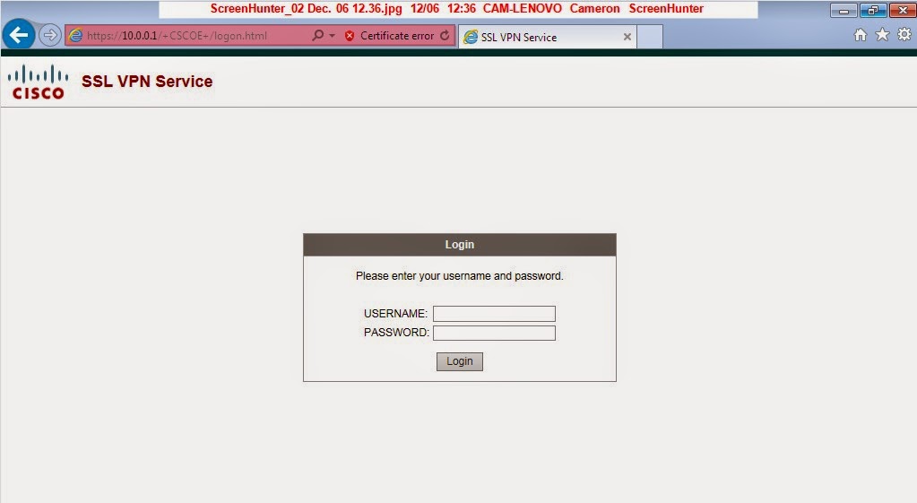
- Users will connect to https://10.0.0.1/Test to sign into the VPN
- We will use a self signed certificate generated on the ASA
- Users will be authenticated against a local database
- Once connected, users will only be able to access https://10.0.0.15

We're starting with a totally clean ASA so first up we need to configure the interface:

ciscoasa(config)# int g0
ciscoasa(config-if)# ip address 10.0.0.1 255.255.255.0
ciscoasa(config-if)# nameif inside
INFO: Security level for "inside" set to 100 by default.
ciscoasa(config-if)# no shut

Now lets lay out the steps required for a VPN to work:

- Generate rsa keys
- create a self signed certificate
- enable webvpn
- create a pool of addresses for the VPN
- create a default group policy
- create a specific group policy
- bypass the interface ACLs
- ensure the VPN traffic is not NATed
- create a tunnel group
- configure user accounts

It looks like a lot, but it's actually quite simple, lets get cracking:

Create keys and certificate:


ciscoasa(config)# crypto key generate rsa label sslvpnkey
INFO: The name for the keys will be: sslvpnkey
Keypair generation process begin. Please wait...
ciscoasa(config)# crypto ca trustpoint localtrust
ciscoasa(config-ca-trustpoint)# enrollment self
ciscoasa(config-ca-trustpoint)# fqdn sslvpn.test.com
ciscoasa(config-ca-trustpoint)# subject-name CN=sslvpn.test.com
ciscoasa(config-ca-trustpoint)# keypair sslvpnkey
ciscoasa(config-ca-trustpoint)# crypto ca enroll localtrust noconfirm

% The fully-qualified domain name in the certificate will be: sslvpn.test.com
ciscoasa(config)# ssl trust-point localtrust inside


The last line is important here, typically we would use the outside interface of the ASA as the whole point of the VPN is terminate traffic from the Internet, but in this case I've just used the inside interface.

Enable webvpn


ciscoasa(config)# webvpn
ciscoasa(config-webvpn)# enable inside

ciscoasa(config-webvpn)# svc enable

Create an address pool for the VPN users:


ciscoasa(config)# ip local pool VPN 10.0.1.1-10.0.1.100 mask 255.255.255.0

Create a default group policy and specific group policy


The default policy is one that will apply to all users and is typically where would configure name servers and other global attributes.  The specific policy can apply to groups of users, for instance you might have one for IT employees and a different one for sales employees.

ciscoasa(config-webvpn)# group-policy DfltGrpPolicy attributes
ciscoasa(config-group-policy)# dns-server value 10.0.0.2
ciscoasa(config-group-policy)# wins-server value 10.0.0.3
ciscoasa(config-group-policy)# vpn-tunnel-protocol svc webvpn

ciscoasa(config-group-policy)# address-pools value VPN

ciscoasa(config)# group-policy IT internal
ciscoasa(config)# group-policy IT attributes
ciscoasa(config-group-policy)# banner value IT Remote Access
ciscoasa(config-group-policy)# vpn-tunnel-protocol webvpn
ciscoasa(config-group-policy)# webvpn


Here we would configure specific rules for IT users, such as what URLs are accessible, but we'll just leave it as default for now.

Configure ACL bypass:


ciscoasa(config)# sysopt connection permit-vpn

NAT exemption:


ciscoasa(config)# access-list no_nat extended permit ip 10.0.1.0 255.255.255.0 10.0.0.0 255.255.255.0
ciscoasa(config)#nat (inside) 0 access-list no_nat

Create a tunnel group:


ciscoasa(config)# tunnel-group ITSSL type remote-access
ciscoasa(config)# tunnel
ciscoasa(config)# tunnel-group ITSSL webvpn-attributes
ciscoasa(config-tunnel-webvpn)# group-alias IT enable
ciscoasa(config-tunnel-webvpn)# group-url https://10.0.0.1/Test enable


Create user accounts:


ciscoasa(config)# username bob password testpass
ciscoasa(config)# username bob attributes
ciscoasa(config-username)# service-type remote-access


And that's it, we should now have a connection working, lets test it out:


Monday 1 December 2014

IPsec

Configuring IPsec


There are four key outcomes from using IPsec which will secure our data:
•    Confidentiality
•    Data integrity
•    Authentication
•    Antireplay

Let’s run through the process a device will go through to set up an IPsec connection to a peer:

1.    IKE Phase 1


The first step involved in a tunnel will be to negotiate the Internet Key Exchange phase 1 tunnel.  There are two modes for this, Main Mode which uses a six packet exchange and Aggressive mode which uses a three packet exchange.  Main mode is considered more secure and is the default mode.  This tunnel is only used for management of the tunnel and no user data is forwarded over it.  There are five items which must be in agreement between the two endpoints before a tunnel can be set up.
•    Hash algorithm
•    Encryption algorithm
•    Diffie-Hellman group
•    Authentication method
•    Lifetime
The lifetime is the only one which doesn’t have to match exactly, as the lower of the two (if they differ) will be used for the tunnel.

2.    Diffie-Hellman key exchange


Once the phase 1 policy is agreed, using the group that has been agreed to in phase 1, a symmetrical key is generated which both ends will use to encrypt the data.

3.    Authenticate the peer


This is the last piece of phase 1 and whichever method agreed to in the phase 1 policy will be used, the options are RSA signatures or pre-shared keys.  Once this is in place we now have a phase 1 tunnel.

Now that we have a management tunnel in place, the two devices must now create a second tunnel that will be used for the actual data.  The devices can use this phase 1 tunnel to negotiate and create the phase 2 tunnel.  This tunnel will use the hashing and encryption algorithms specified in the device configuration, which means that when we are configuring a VPN, we specify the hashing and encryption algorithms for phase 1 and phase 2.

Once we the phase 2 tunnel built then the devices will encrypt the traffic.  Any packet capture between the devices will just look like an encrypted stream of traffic between the two peers.

Let’s build our own VPN connection now to put in place what we have learnt.

I’m using a very simplified topology of two IOS routers directly connected to each other, that direct connection is simulating the Internet.  On each router I have a loopback interface which is simulating an internal network behind the router, and we will configure our VPN to encrypt all traffic between the two networks.


Remembering what we need to configure to get the connection working, this is what we will use for Phase 1:
•    Hash – SHA.  This is generally considered more secure than MD5
•    Authentication – Pre-shared key
•    Group – Diffie-Hellman group, we will use group 5
•    Lifetime – we will use 3600
•    Encryption – AES 256
For phase 2 we will use SHA and AES256 again.

Let’s put that in place on R1:

R1(config)#crypto isakmp policy 5
R1(config-isakmp)#authentication pre-share
R1(config-isakmp)#encryption aes 256
R1(config-isakmp)#hash sha
R1(config-isakmp)#group 5
R1(config-isakmp)#lifetime 3600
R1(config-isakmp)#exit
R1(config)#crypto isakmp key secretkey address 10.0.0.2
R1(config)#access-list 100 permit ip 172.16.31.0 0.0.0.255 192.168.0.0 0.0.0.255
R1(config)#crypto ipsec transform-set TESTSET esp-sha-hmac esp-aes 256
R1(cfg-crypto-trans)#mode tunnel
R1(config)#crypto map TESTCMAP 1 ipsec-isakmp
R1(config-crypto-map)#match address 100
R1(config-crypto-map)#set transform-set TESTSET
R1(config-crypto-map)#set peer 10.0.0.2
R1(config-crypto-map)#exit
R1(config)#int fa0/0
R1(config-if)#crypto map TESTCMAP


This looks like quite a bit of config, but let’s quickly run through it.  First we establish an ISAKMP polic (phase 1).  We can have multiple policies on each device, and as long as one of them matches then a tunnel can be formed.  We apply our chosen configuration within the phase 1 policy.  Second we define a pre-shared key to use with a remote router and assign it the address of the other end.  Now we create an access-list which will contain all of the traffic which we will want to be encrypted and sent across the tunnel.  Phase 2 is created next and we assign it the chosen configuration, similar to phase 1 except it’s all done in one line.  We set it to tunnel mode which means that the router will take any traffic matching the access-list and encrypt them inside an IPsec packet.  Transport mode is the other option but that is only for traffic between the devices.  Create a crypto map and then apply it to an interface, which causes the router to automatically capure traffic matching the ACL specified in the crypto map and apply the chosen configuration to it, in this cause use the VPN tunnel.
Now let’s apply the same but inverse configuration to R2 and bring up a tunnel.

R1#show crypto isakmp sa detail
Codes: C - IKE configuration mode, D - Dead Peer Detection
       K - Keepalives, N - NAT-traversal
       T - cTCP encapsulation, X - IKE Extended Authentication
       psk - Preshared key, rsig - RSA signature
       renc - RSA encryption
IPv4 Crypto ISAKMP SA

C-id  Local           Remote          I-VRF    Status Encr Hash Auth DH Lifetime Cap.

1001  10.0.0.1        10.0.0.2                 ACTIVE aes  sha  psk  5  00:47:12
       Engine-id:Conn-id =  SW:1

IPv6 Crypto ISAKMP SA


R1#show crypto ipsec sa

interface: FastEthernet0/0
    Crypto map tag: TESTCMAP, local addr 10.0.0.1

   protected vrf: (none)
   local  ident (addr/mask/prot/port): (172.16.31.0/255.255.255.0/0/0)
   remote ident (addr/mask/prot/port): (192.168.0.0/255.255.255.0/0/0)
   current_peer 10.0.0.2 port 500
     PERMIT, flags={origin_is_acl,}
    #pkts encaps: 4, #pkts encrypt: 4, #pkts digest: 4
    #pkts decaps: 4, #pkts decrypt: 4, #pkts verify: 4
    #pkts compressed: 0, #pkts decompressed: 0
    #pkts not compressed: 0, #pkts compr. failed: 0
    #pkts not decompressed: 0, #pkts decompress failed: 0
    #send errors 10, #recv errors 0

     local crypto endpt.: 10.0.0.1, remote crypto endpt.: 10.0.0.2
     path mtu 1500, ip mtu 1500, ip mtu idb FastEthernet0/0
     current outbound spi: 0xA6EC9D4E(2800524622)
     PFS (Y/N): N, DH group: none

     inbound esp sas:
      spi: 0xC7236551(3340985681)
        transform: esp-256-aes esp-sha-hmac ,
        in use settings ={Tunnel, }
        conn id: 1, flow_id: SW:1, sibling_flags 80000046, crypto map: TESTCMAP
        sa timing: remaining key lifetime (k/sec): (4571197/3545)
        IV size: 16 bytes
        replay detection support: Y
        Status: ACTIVE

     inbound ah sas:

     inbound pcp sas:

     outbound esp sas:
      spi: 0xA6EC9D4E(2800524622)
        transform: esp-256-aes esp-sha-hmac ,
        in use settings ={Tunnel, }
        conn id: 2, flow_id: SW:2, sibling_flags 80000046, crypto map: TESTCMAP
        sa timing: remaining key lifetime (k/sec): (4571197/3545)
        IV size: 16 bytes
        replay detection support: Y
        Status: ACTIVE

     outbound ah sas:

     outbound pcp sas:


R1#show crypto engine connections active
Crypto Engine Connections

   ID  Type    Algorithm           Encrypt  Decrypt LastSeqN IP-Address
    1  IPsec   AES256+SHA                0        4        4 10.0.0.1
    2  IPsec   AES256+SHA                4        0        0 10.0.0.1
 1001  IKE     SHA+AES256                0        0        0 10.0.0.1

 
Note you'll see a few send errors in the phase 2, this is because I initally forgot to attach the transform set on R2 to the crypto map and the VPN failed to come up.

Public Key Infrastructure

We cannot properly understand and implement secure technologies without understanding the principles behind them.  So to continue I this vain we’ll take a deeper look into the principles of public and private keys, and how we use them in our security.

There are a number of different protocols in use today to generate key-pairs:

•    RSA – primarily used for authentication
•    DH – Whilst the algorithm is asymmetric, it generates symmetric keys, and we typically use this in conjunction with 3DES and AES.
•    ElGamal – used with DH
•    DSA – Digital Signature Algorithm
•    ECC – Elliptical Curve Cryptography

Public Keys in use


Both parties who want to communicate will have a public and private key pair.  They are both enrolled with a Certificate Authority (CA), which used the public keys of both and created their digital certificates.  To communicate, we now send our digital certificate to the other party.  The receiving party will verify that the certificate was issued by a trusted CA.  Now that both parties have each other’s public keys, they can communicate securely. 

Certificate Authorities


We briefly mentioned Certificate Authorities (CA) above, so let’s talk a bit more about the role they play for us.  They are an entity which has the ability to create and issue digital certificates.  These certificates include the Fully Qualified Domain Name (FQDN) of the device along with its IP address and public key, and also contain validity dates to ensure that the certificate has no expired.  Most web browsers come with a list of CAs which are trusted, thus relieving us of the problem of being able to verify the identity of these CAs
A root certificate is the certificate associated with the CA and contains the CAs public key.  An identity certificate is similar, but it describes a client and contains that client’s public key.

Digital certificates will contain either all or most of the following:
•    Serial number of the certificate
•    Subject
•    Signature algorithm
•    Signature
•    Issuer
•    Valid from
•    Valid to
•    Key usage
•    Public key
•    Thumbprint algorithm
•    Thumbprint
•    Certificate revocation list location

Public Key Standards


•    PKCS 1 – RSA
•    PKCS 3 – Diffie-Hellman
•    PKCS 7 – format of a response to a PKCS 10 request
•    PKCS 10 – format of a certificate request sent to a CA.
•    PKCS 12 – format for storing public and private keys using a symmetric password

Implementing PKI


Single Root CA


A typical solution for a small environment is to have one single CA server handling all requests; however there is no fault tolerance in this case.

Hierarchical CA with Subordinate CAs


Here we have a root CA which delegates the authority to subordinate CAs to create and assign identity certificates. 

Cross-certifying CAs


In this situation we have multiple CAs acting at the same level.  Clients of either CA will trust the signatures of the other CA.

Configuring certificates on an ASA:


ciscoasa(config)# crypto key generate rsa label TestPair modulus 2048 noconfirm
INFO: The name for the keys will be: TestPair
Keypair generation process begin. Please wait...

ciscoasa(config)# crypto ca trustpoint TestCA
ciscoasa(config-ca-trustpoint)# keypair TestPair
ciscoasa(config-ca-trustpoint)# id-usage ssl-ipsec
ciscoasa(config-ca-trustpoint)# no fqdn
ciscoasa(config-ca-trustpoint)# subject-name CN=ciscoasa
ciscoasa(config-ca-trustpoint)# enrollment url http://192.168.1.1
ciscoasa(config-ca-trustpoint)# exit
ciscoasa(config)# crypto ca authenticate TestCA nointeractive
ciscoasa(config)# crypto ca enroll TestCA noconfirm


VPNs and cryptography

Virtual Private Network (VPN)


A VPN is a method of creating a local network between two devices which are not local to each other.  For instance we might have a device in Auckland and a device in London, with a VPN, we can configure a connection so it’s as if they are on the same LAN.  VPNs came around because the cost of a dedicated line between sites is much higher than implementing a VPN over the Internet. 

Types of VPN


•    IPsec – typically used for site-to-site connections, but can be used for remote-access as well, it implements security at layer 3
•    SSL – security at layer 4, typically used for remote-access VPNs
•    MPLS – provided by a service provider to connect multiple sites that a company as.  No encryption by default but IPsec can be added on top

Benefits of a VPN


The benefits of a VPN hark back to the beginning of this blog where we talked about the key ingredients for data security:
•    Confidentiality
•    Integrity
•    Authentication

Cryptography basics


A cipher is an algorithm that basically lays out how to change a piece of data which we want to keep secret, into an unintelligible piece of data, and then return that data back to what we want, when we want it.

Substitution – Substituting one character for another. 
Polyalphabetic – Using multiple alphabets and switching between them to introduce more complexity
Transposition – Use many different options including the rearrangement of letters.

A key is instructions for how to reassemble the characters back into the correct data. 

A block cipher is a symmetric key that operates on chunks of data called blocks.  Many of the well-known encryption algorithms are symmetric block ciphers.

A stream cipher is also a symmetric key cipher where it is encrypted one bit at a time.

We’ve just briefly mentioned the concept of symmetric and asymmetric keys here, so let’s explore what we mean when we talk about those.

A symmetric algorithm means that exactly the same key is used to encrypt and decrypt the data.  Obviously this means that keeping the key secret is of the utmost importance, because anyone with the key can decrypt it.  This process is used for most of the data we encrypt today simply because it uses much less overhead than asymmetric encryption. 

An asymmetric algorithm is the opposite of this.  When we encrypt the data with one key, we need a different key to decrypt it.  Once it’s encrypted, it’s impossible to decrypt with that same key.  When we implement this, we use the concept of public and private keys.  If someone wants to send us some data, we will give them our public key and they will encrypt the data using this key.  Then when we receive the data, it can only be decrypted with our private key which we have kept secret.

Continuing with our key terms to understand is the concept of hashing.  This is a method used to verify data integrity.  What happens is that we use a process to create a small size value which is associated with that data.  It is only possible to generate that value if the data is exactly the same, so when a hash is set along with the data, we can calculate the hash ourselves, and if they match then we can be confident that the data has not been modified.  The most common algorithms in place are MD5, SHA-1 and SHA-2.  However this does not stop a malicious person manipulating both the data and the hash.

We can use the Hashed Message Authentication Code (HMAC) to calculate the hash and use a secret key to ensure it cannot be modified by unknown people.  This makes it impossible to recalculate a hash without the receiver knowing.

Digital Signatures use a combination of all of these methods to verify that something comes from exactly who it says it comes from.  The process follows like this:  We create a hash of the packet which we are transmitting, and then we encrypt that hash with our private key.  This encrypted hash is called a digital signature and is sent along with the data.  The receiver can then decrypt the hash using our public key and compare it to the hash which they generate themselves.  If the two hashes match then the receiver can be sure that both the data is untouched and that it comes from the correct person.

IPsec


We’ll go into IPsec in more detail later but here are some key things to know:

•    ESP and AH – these are the two protocols we can use to implement IPsec.  ESP is much more frequently used than AH.
•    Encryption algorithms – DES, 3DES, AES
•    Hashing algorithms – MD5, SHA
•    Authentication algorithms – Pre-shared keys, RSA digital signatures
•    Key management – Diffie-Hellman (DH) ca be used to dynamically generate symmetrical keys.  Internet Key Exchange (IKE) does most of the key negotiation.

SSL


Secure Sockets Layer is the protocol we use when we connect to a web server over https instead of http.  When we connect to https, the browser requests that the server identifies itself using its digital certificate.  The browser verifies the certificate using the digital signature attached.

Thursday 27 November 2014

Introducing the ASA

Meet the ASA


Finally the time has come for us to talk about a dedicated firewall device.  The ASA has been around for a long time, although it has often been called the PIX firewall.

There are a number of different hardware models of the ASA, however the all behave pretty much exactly the same, with the exception of the 5505.  The 5505 has an inbuilt switch model and uses VLANs rather than physical interfaces for its IP addressing and configuration.  However all the same principles apply.  The 5510 up to the 5585 gradually move up in terms of capacity but for all intents and purposes can be treated the same, there also exists the Firewall Services Module which is a blade which can be plugged in to a compatible switch.

I won’t go into all the features which the ASA supports, but it has all the features you would expect from an enterprise firewall.

The basics


The ASA uses the concepts of security levels which are assigned to interfaces.  The security level is a number between 0 and 100 and correlates to the trust you would place in that network.  By default, an interface labelled ‘inside’ will have the security level 100 while an interface labelled ‘outside’ will have the security level 0.  By default (and this is very important) if a packet is coming from a higher security level interface than it is destined for (eg, going from inside to outside) that traffic will be permitted even with no matching access-list.  However the inverse of this is also true, any traffic going from a lower security to a higher security interface will be blocked.  We also need to remember, that just like an IOS router, there is an implicit deny at the end of every access list, so if there are no matching permit statements that traffic will be dropped.

Let’s get into the fun stuff, we’re going to remove our central router and replace it with an ASA.  We’re going to playing with a 5520 running version 8.4(2) so if you’re using a 5505 at home then the commands will differ slightly, however the theory behind them remains the same.


ciscoasa(config)# hostname CentralFW
CentralFW(config)# int g2
CentralFW(config-if)# ip address 192.168.21.1 255.255.255.0
CentralFW(config-if)# nameif inside
INFO: Security level for "inside" set to 100 by default.
CentralFW(config-if)# no shut
CentralFW(config-if)# int g1
CentralFW(config-if)# ip address 172.16.31.1 255.255.255.0
CentralFW(config-if)# nameif dmz
INFO: Security level for "dmz" set to 0 by default.
CentralFW(config-if)# security-level 50
CentralFW(config-if)# no shut
CentralFW(config-if)# int g0
CentralFW(config-if)# ip address 45.45.45.1 255.255.255.0
CentralFW(config-if)# nameif outside
INFO: Security level for "outside" set to 0 by default.
CentralFW(config-if)# no shut


We can also configure the ASA to act as a DHCP server, so first let’s change the configuration of our internal device to receive their IP addresses automatically.
InternalRTR(config)#int f0/0
InternalRTR(config-if)#no ip address 192.168.21.20 255.255.255.0
InternalRTR(config-if)#ip address dhcp

CentralFW(config)# dhcpd address 192.168.21.10-192.168.21.50 inside
CentralFW(config)# dhcpd enable inside


If we go back to InternalRTR now and check it’s IP address:

InternalRTR#show ip int br
Interface                  IP-Address      OK? Method Status                Protocol
FastEthernet0/0            192.168.21.10   YES DHCP   up                    up


We also need to define routing just like a router, so let’s define a static route to the internet:

CentralFW(config)# route outside 0.0.0.0 0.0.0.0 45.45.45.20

NAT


NAT is where things can get very confusing on the ASA.  When Cisco released version 8.3 they completely rewrote the way NAT is configured on the firewall.  Whilst you will be expected to know how to configure NAT on a pre 8.3 device, this blog will go over NAT configuration on the newer devices.
We want to set up NAT like we did earlier, so that when hosts on the inside access hosts on the outside, they are translated to the external interface of the firewall.

CentralFW(config)# object network InternalNet
CentralFW(config-network-object)# subnet 192.168.21.0 255.255.255.0
CentralFW(config-network-object)# nat (inside,outside) static interface


Let’s setup an SSH session from inside to outside again to verify it is working:

ExternalRTR#show users
    Line       User       Host(s)              Idle       Location
*  2 vty 0     admin      idle                 00:00:00 45.45.45.1


Note: on a pre 8.3 ASA instead of defining the NAT as part of the object group – we would define it as line like this:

nat (inside,outside) 1 source dynamic InternalNet interface

Now we’re going to want to define some access-lists to lock down this traffic a bit better than it is currently.

CentralFW(config)# access-list inside_to_outside extended permit tcp object InternalNet any eq ssh log
CentralFW(config)# access-group inside_to_outside in interface inside


We need to be very clear with what we are permitting now, because now that we have defined an access-list for traffic entering the inside interface, all traffic that is not explicitly permitted will be dropped.

One of the great tools that comes with the ASA is the packet-tracer command which allows us to simulate traffic and see the processing steps the firewall would take as if it were a real packet.  Lets try it for ssh traffic (which will be allowed) and http traffic (which will be dropped).

CentralFW# packet-tracer input inside tcp 192.168.21.10 5342 45.45.45.20 ssh detailed

Phase: 1
Type: ROUTE-LOOKUP
Subtype: input
Result: ALLOW
Config:
Additional Information:
in   45.45.45.0      255.255.255.0   outside

Phase: 2
Type: ACCESS-LIST
Subtype: log
Result: ALLOW
Config:
access-group inside_to_outside in interface inside
access-list inside_to_outside extended permit tcp object InternalNet any eq ssh log
Additional Information:
 Forward Flow based lookup yields rule:
 in  id=0xbc3236e0, priority=13, domain=permit, deny=false
        hits=0, user_data=0xb9466b40, cs_id=0x0, use_real_addr, flags=0x0, protocol=6
        src ip/id=192.168.21.0, mask=255.255.255.0, port=0
        dst ip/id=0.0.0.0, mask=0.0.0.0, port=22, dscp=0x0
        input_ifc=inside, output_ifc=any

Phase: 3
Type: IP-OPTIONS
Subtype:
Result: ALLOW
Config:
Additional Information:
 Forward Flow based lookup yields rule:
 in  id=0xbc2a6700, priority=0, domain=inspect-ip-options, deny=true
        hits=12, user_data=0x0, cs_id=0x0, reverse, flags=0x0, protocol=0
        src ip/id=0.0.0.0, mask=0.0.0.0, port=0
        dst ip/id=0.0.0.0, mask=0.0.0.0, port=0, dscp=0x0
        input_ifc=inside, output_ifc=any

Phase: 4
Type: NAT
Subtype:
Result: ALLOW
Config:
object network InternalNet
 nat (inside,outside) static interface
Additional Information:
Static translate 192.168.21.10/5342 to 45.45.45.1/5342
 Forward Flow based lookup yields rule:
 in  id=0xbc3215e0, priority=6, domain=nat, deny=false
        hits=2, user_data=0xbc3116c8, cs_id=0x0, use_real_addr, flags=0x0, protocol=0
        src ip/id=192.168.21.0, mask=255.255.255.0, port=0
        dst ip/id=0.0.0.0, mask=0.0.0.0, port=0, dscp=0x0
        input_ifc=inside, output_ifc=outside

Phase: 5
Type: IP-OPTIONS
Subtype:
Result: ALLOW
Config:
Additional Information:
 Reverse Flow based lookup yields rule:
 in  id=0xbc3055c8, priority=0, domain=inspect-ip-options, deny=true
        hits=4, user_data=0x0, cs_id=0x0, reverse, flags=0x0, protocol=0
        src ip/id=0.0.0.0, mask=0.0.0.0, port=0
        dst ip/id=0.0.0.0, mask=0.0.0.0, port=0, dscp=0x0
        input_ifc=outside, output_ifc=any

Phase: 6
Type: FLOW-CREATION
Subtype:
Result: ALLOW
Config:
Additional Information:
New flow created with id 13, packet dispatched to next module
Module information for forward flow ...
snp_fp_tracer_drop
snp_fp_inspect_ip_options
snp_fp_tcp_normalizer
snp_fp_translate
snp_fp_adjacency
snp_fp_fragment
snp_ifc_stat

Module information for reverse flow ...
snp_fp_tracer_drop
snp_fp_inspect_ip_options
snp_fp_translate
snp_fp_tcp_normalizer
snp_fp_adjacency
snp_fp_fragment
snp_ifc_stat

Result:
input-interface: inside
input-status: up
input-line-status: up
output-interface: outside
output-status: up
output-line-status: up
Action: allow


This shows all the processing steps the firewall takes on traffic that is coming from 192.168.21.10 to 45.45.45.20 on ssh on the inside interface.  Pay particular attention to Phase 2 and Phase 4, which show the ACL it is hitting, and the NAT rule.  Now let’s try it for http:

CentralFW# packet-tracer input inside tcp 192.168.21.10 5342 45.45.45.20 http detailed

Phase: 1
Type: ROUTE-LOOKUP
Subtype: input
Result: ALLOW
Config:
Additional Information:
in   45.45.45.0      255.255.255.0   outside

Phase: 2
Type: ACCESS-LIST
Subtype:
Result: DROP
Config:
Implicit Rule
Additional Information:
 Forward Flow based lookup yields rule:
 in  id=0xbc323778, priority=11, domain=permit, deny=true
        hits=0, user_data=0x5, cs_id=0x0, flags=0x0, protocol=0
        src ip/id=0.0.0.0, mask=0.0.0.0, port=0
        dst ip/id=0.0.0.0, mask=0.0.0.0, port=0, dscp=0x0
        input_ifc=inside, output_ifc=any

Result:
input-interface: inside
input-status: up
input-line-status: up
output-interface: outside
output-status: up
output-line-status: up
Action: drop
Drop-reason: (acl-drop) Flow is denied by configured rule

Here we see that the traffic is dropped in phase 2, because it is not specified in the ACL.

That’s a basic rundown on how to use an ASA, but of course there’s much more that can be done with them.

IOS Zone-based firewall


When we configure a zone-based firewall, we place interfaces into security zones.  All our policies reference zones instead of interfaces, in this way we can add interfaces to a zone without configuring a whole bunch of new roles.  It’s a fairly common way of implementing a firewall, with Juniper also using the concept of security zones in their SSG and SRX lines. 

Zone-based firewall features:
•    Stateful inspection
•    Application inspection
•    Packet filtering
•    URL filtering
•    Transparent firewall
•    Support for virtual routing ad forwarding (VRF)
•    ACLs are not required as a prerequisite for the policy

Interfaces can only belong to a single zone.  There also exists a self-zone which is used for any traffic destined for the router itself.  Once we place an interface in a zone, no traffic is allowed from that zone to any other zone unless we specifically permit it.  However all traffic is allowed between interfaces in the same zone.  To allow traffic between zones, first we create a zone-pair, which identifies the source and destination zones and applies a policy to traffic which matches that zone pair.

That is all fairly generic information for a zone-based firewall, so let’s see how this works on a Cisco IOS router.

•    Class maps – This is what will identify the traffic.  Traffic can be matched on anything from layer 3 through to layer 7 of the OSI model, and it can refer to ACLs to identify traffic. A class map consists of match statements and can have multiple of those.  We can also set it match all so that all statements have to match, or match-any, in which any of the statements can match.
•    Policy maps – These define the actions that are taken on the traffic.  Policy maps are processed in order.  The most common actions that can be taken are inspect, permit, drop or log.
•    Service policies – Where policies are applied from a policy map to a zone pair.

So let’s go ahead and create some policies apply to our configuration:


First let’s define a class map that will match on management traffic which we will define as telnet, ssh, https and icmp.

R1(config)#class-map type inspect match-any MGMTMAP
R1(config-cmap)#match protocol telnet
R1(config-cmap)#match protocol ssh
R1(config-cmap)#match protocol icmp
R1(config-cmap)#match protocol https


Now we need to define a policy map which calls on this class map.

R1(config)#policy-map type inspect MGMTPOLMAP
R1(config-pmap)#class type inspect MGMTMAP
R1(config-pmap-c)#inspect


Now let’s create our three zones:

R1(config)#zone security internal
R1(config-sec-zone)#exit
R1(config)#zone security external
R1(config-sec-zone)#exit
R1(config)#zone security dmz
R1(config-sec-zone)#exit


Now we need to create a zone-pair and apply a policy map to it:

R1(config)#zone-pair security in-to-dmz source internal destination dmz
R1(config-sec-zone-pair)#service-policy type inspect MGMTPOLMAP


The last step we need to configure is to place the interfaces in their correct zones:

R1(config)#int g2/0
R1(config-if)#zone-member security internal
R1(config-if)#exit
R1(config)#int f1/0
R1(config-if)#zone-member security dmz
R1(config-if)#exit
R1(config)#int f0/0
R1(config-if)#zone-member security external


What we have created here is to allow the internal network to access the DMZ only on telnet, ssh, https and icmp, so let’s give it a test: (note that I’ve changed to using routers in GNS3 to act as end devices, Virtualbox was killing my machine!)

InternalRTR#ping 172.16.31.20

Type escape sequence to abort.
Sending 5, 100-byte ICMP Echos to 172.16.31.20, timeout is 2 seconds:
!!!!!
Success rate is 100 percent (5/5), round-trip min/avg/max = 32/65/164 ms


InternalRTR#telnet 172.16.31.20 80
Trying 172.16.31.20, 80 ...
% Connection timed out; remote host not responding

InternalRTR#telnet 172.16.31.20
Trying 172.16.31.20 ... Open


We can see that ICMP and telnet are being allowed through, but port 80 is blocked.

We can also run a debug on the router to verify it is being blocked:

*Nov 27 10:41:58.151: FIREWALL*: NEW PAK 67181CE0 (0:192.168.21.20:52467) (0:172.16.31.20:80) tcp
*Nov 27 10:41:58.151: FIREWALL*: DROP feature object 0xAAAA0005 found
*Nov 27 10:41:43.247: FIREWALL* sis 67EF6240: L4 result: PASS packet 0x67181CE0 (192.168.21.20:22967) (172.16.31.
R1#20:22) bytes 24


Note that because we have not defined a zone-pair between the inside and outside networks, all traffic is allowed at this stage.  We would need to follow a similar process to above to lock that down.  There is a slight difference with the self-zone, where even if we define a zone-pair but have no policy in it, traffic will be allowed between the self-zone and any other zone, however with two regular zones, if we have a zone-pair defined with no policy then all traffic will be dropped.
We can also create all of this using the Cisco Configuration Professional interface; however I won’t be going into any of that configuration here.  You can download the software from Cisco with a valid

So now let’s finish off this by securing the firewall to have the same access as we configured with the access-lists in an earlier post.

To recap this is the access to be allowed:

•    Everyone on the internal network can access the Internet for web browsing
•    Everyone on the internal network can access the DMZ but only for management (SSH, HTTPS and RDP)
•    Everyone on the internet can only access the web server (172.16.31.20) but only on HTTP and HTTPS

So far we have configured access from the internal network to the DMZ for ssh, https, telnet and icmp so we need to change that configuration slightly.

R1(config)#class-map type inspect match-any MGMTMAP
R1(config-cmap)#no match protocol telnet
R1(config-cmap)#no match protocol icmp
R1(config)#ip access-list extended RDP
R1(config-ext-nacl)#permit tcp any any eq 3389
R1(config)#class-map type inspect MGMTMAP
R1(config-cmap)#match access-group name RDP


Now we should access from the internal to the DMZ locked down to just SSH, HTTPS and RDP:

*Nov 27 12:55:42.475: FIREWALL*: NEW PAK 67181CE0 (0:192.168.21.20:54688) (0:172.16.31.20:23) tcp
*Nov 27 12:55:42.475: FIREWALL*: DROP feature object 0xAAAA0005 found

*Nov 27 12:56:07.395: FIREWALL* sis 67EF6560: Pak 0x66F549FC IP: s=172.16.31.20 (FastEthernet1/0), d=192.168.21.20 (GigabitEthernet2/0), len 20, proto=tcp
*Nov 27 12:56:07.395: FIREWALL* sis 67EF6560: L4 result: PASS packet 0x66F549FC (172.16.31.20:3389) (192.168.21.20:11910) bytes 20


Let’s lock down our access for the outside now.  Everyone should be able to access the web server, but only on http and https

R1(config)#ip access-list extended WEBACL
R1(config-ext-nacl)#permit ip any host 172.16.31.20

R1(config)#class-map type inspect match-any WEBMAPPORTS
R1(config-cmap)#match protocol http
R1(config-cmap)#match protocol https
R1(config-cmap)#exit
R1(config)#class-map type inspect match-all WEBMAP
R1(config-cmap)#match class-map WEBMAPPORTS
R1(config-cmap)#match access-group name WEBACL
R1(config-cmap)#exit
R1(config)#policy-map type inspect WEBPOLMAP
R1(config-pmap)#class type inspect WEBMAP
R1(config-pmap-c)#inspect

R1(config)#zone-pair security out-to-dmz source external destination dmz
R1(config-sec-zone-pair)#service-policy type inspect WEBPOLMAP


If we run through what we do above, we create an access-list only allowing traffic to the destination 172.16.31.20.  Then we create a class map that will match on either http and https traffic.  Now we create another class-map that will only match on both the destination IP and ports.  The policy map then inspects that class map, and in turn the zone-pair inspects that policy map.

*Nov 27 14:27:03.839: FIREWALL* sis 675C3AA0: L4 result: PASS packet 0x66F549FC (172.16.31.20:80) (45.45.45.20:47585) bytes 20
*Nov 27 14:27:49.383: FIREWALL*: NEW PAK 66F54590 (0:45.45.45.20:30237) (0:172.16.31.20:22) tcp
*Nov 27 14:27:49.383: FIREWALL*: DROP feature object 0xAAAA000C found


Looks like our configuration is working – port 80 is accessible from the outside, but port 22 is blocked.

We can also use some show commands to have a look at what is happening on the firewall:

R1#show class-map type inspect
 Class Map type inspect match-all WEBMAP (id 11)
   Match class-map WEBMAPPORTS
   Match access-group name WEBACL

 Class Map type inspect match-any WEBMAPPORTS (id 10)
   Match protocol http
   Match protocol https

 Class Map type inspect match-any MGMTMAP (id 1)
   Match protocol ssh
   Match protocol https
   Match access-group name RDP


Note – I set up an SSH session from my internal device to my external device and then issued this command:

R1#show policy-map type inspect zone-pair in-to-dmz sessions

policy exists on zp in-to-dmz
 Zone-pair: in-to-dmz

  Service-policy inspect : MGMTPOLMAP

    Class-map: MGMTMAP (match-any)
      Match: protocol ssh
        2 packets, 48 bytes
        30 second rate 0 bps
      Match: protocol https
        0 packets, 0 bytes
        30 second rate 0 bps
      Match: access-group name RDP
        0 packets, 0 bytes
        30 second rate 0 bps

   Inspect

      Number of Established Sessions = 1
      Established Sessions
        Session 675C4720 (192.168.21.20:40743)=>(172.16.31.20:22) ssh:tcp SIS_OPEN
          Created 00:00:39, Last heard 00:00:33
          Bytes sent (initiator:responder) [251:403]


    Class-map: class-default (match-any)
      Match: any
      Drop
        2 packets, 48 bytes


The last thing to configure for this post is to get some NAT going.  We haven’t set up anything for internal to external, so let’s configure it so that any host on the internal can get to any host on the outside network, but we’re only going to allow ssh, http, https, pop3, smtp and imap.

We’ll follow exactly the same process as before, class-map, policy-map, zone-pair.  We’ll add the NAT right at the end.

R1(config)#class-map type inspect match-any INTOOUTMAP
R1(config-cmap)#match protocol http
R1(config-cmap)#match protocol https
R1(config-cmap)#match protocol ssh
R1(config-cmap)#match protocol smtp
R1(config-cmap)#match protocol imap
R1(config-cmap)#match protocol pop3

R1(config)#policy-map type inspect INTOOUTPOLMAP
R1(config-pmap)#class type inspect INTOOUTMAP
R1(config-pmap-c)#inspect

R1(config)#zone-pair security IN_TO_OUT source internal destination external
R1(config-sec-zone-pair)#service-policy type inspect INTOOUTPOLMAP


That should be enough to enable the ports out that we would like, now we just need to add the NAT configuration:

R1(config)#access-list 10 permit 192.168.21.0 0.0.0.255
R1(config-if)#int fa0/0
R1(config-if)#ip nat outside
R1(config)#int g2/0
R1(config-if)#ip nat inside
R1(config)#ip nat inside source list 10 interface fa0/0 overload


Now we should be able to ssh from our internal network to our external network and when it passes the router it should be translated to the outside interface of the router.  Let’s give it a go:

R1#show policy-map type inspect zone-pair IN_TO_OUT sessions

policy exists on zp IN_TO_OUT
 Zone-pair: IN_TO_OUT

  Service-policy inspect : INTOOUTPOLMAP

    Class-map: INTOOUTMAP (match-any)
      Match: protocol http
        1 packets, 24 bytes
        30 second rate 0 bps
      Match: protocol https
        0 packets, 0 bytes
        30 second rate 0 bps
      Match: protocol ssh
        1 packets, 24 bytes
        30 second rate 0 bps
      Match: protocol smtp
        0 packets, 0 bytes
        30 second rate 0 bps
      Match: protocol imap
        0 packets, 0 bytes
        30 second rate 0 bps
      Match: protocol pop3
        0 packets, 0 bytes
        30 second rate 0 bps

   Inspect

      Number of Established Sessions = 1
      Established Sessions
        Session 675C4D60 (192.168.21.20:64953)=>(45.45.45.20:22) ssh:tcp SIS_OPEN
          Created 00:00:56, Last heard 00:00:14
          Bytes sent (initiator:responder) [419:4351]


    Class-map: class-default (match-any)
      Match: any
      Drop
        13 packets, 592 bytes


Looks like it’s working as we’d expect, and indeed the SSH session is working from that router.  Now let’s verify the NAT:

R1#show ip nat translations
Pro Inside global           Inside local                 Outside local         Outside global
tcp 45.45.45.1:64953   192.168.21.20:64953 45.45.45.20:22    45.45.45.20:22


We can see that the Inside local address is 192.168.21.20 which is the address of the internal device, and the inside global address is 45.45.45.1 which is the ip address of the central router’s external interface, so the NAT is indeed working.

One final check is to see what the external router is seeing:

ExternalRTR#show users
    Line       User       Host(s)              Idle       Location
*  0 con 0                idle                 00:00:00
   2 vty 0     admin      idle                 00:03:01 45.45.45.1


It shows the user admin is logged on from 45.45.45.1, so it’s all working perfectly.

Well that was a fairly lengthy post, but it gives us some great practical knowledge on zone-based firewall.  Next up we’re moving to the ASA.

Wednesday 26 November 2014

Firewall basics

Firewalls


What is a firewall?


I'm sure you all know what a firewall is, but let's give it a basic definition.  It is essentially a device that is designed to stop traffic flowing.  I like to think of it like an inverse of a router, a router is generally designed to get traffic from one place to another, and a firewall is generally designed to stop traffic going from one place to another.  Obviously this is a very simplistic view of things but it's handy to keep in mind when we think about the core concepts behind firewalls.

Typically a firewall is placed at a border of a network which is controlled by you, and a network which is not controlled by you.  In larger organisations firewalls can also be used to segment different parts of the network.  However there is one thing we must keep in mind; which is that we can't just simply place a firewall at the edge and let that be our only line of defense.  If that firewall were to be compromised, we want a comprehensive security infrastructure in place that can mitigate the effect of a firewall being compromised.

There are five different methodologies firewalls can use (and many use multiple, if not all, of these)

  • Static packet filtering – based on layers 3 and 4 of the OSI model.  It does not maintain a session table so every flow of traffic must be configured individually. 
  • Application layer gateway – can operate at layer 3 and higher.  This acts as a proxy between a client and server, no traffic flows directly between the two without first passing through the gateway.  It has the potential to deeply analyse every packet that passes between the client and server, but can be very resource intensive. 
  • Stateful packet filtering – What we think of as firewalls.  Maintains sessions tables so that return traffic doesn't have to explicitly allowed.  However these can still be bypassed by application layer attacks, for example, it is possible to tunnel attack traffic over ports that are allowed.
  • Application inspection – Can analyse protocols up to layer 7 but does not act as a proxy
  • Transparent firewalls – Kind of act like a hidden firewall, they exist at layer 2 instead of a layer 3 hop like a traditional firewall.

Network Address Translation (NAT)


NAT is the process of translating one address to another address.  It is typically used to translate a private IP address on an internal LAN, to a publicly routable IP address.  That is why if you see your IP on your local machine as 192.168.1.5, if you view your IP on the internet it will be something completely different.  NAT is heavily implemented on firewalls because firewalls so often act as the border between a private network and the internet.  In order to understand NAT you'll need to understand these 4 terms:

  • Inside local – the real, private IP on a host
  • Inside global – the IP that the host is mapped to on the internet
  • Outside local – the mapped IP address of a server as it appears to an inside host
  • Outside global – the real, public IP of the outside server.
 Often the outside local and outside global IP addresses are the same, as outside NAT is not so common.

We can also use port address translation (PAT) in order to translate multiple internal private IP's to one public IP.  The translating device uses the port numbers to keep track of the translations.

Firewall design


Here are some best practices to consider when deploying a firewall:

Firewalls should be placed at security boundaries
Primary, but not the only, security device
Firewalls should be written so that they deny all traffic not explicitly permitted instead of the other way around.
All technologies surrounding the firewall must be secure as well, including the routers and switches which connect to it, as well the physical security of the device.
All changes should be documented and subject to a change control so management can always have an accurate view of the state of the firewall.

When we design our firewalls we need to think in terms of enabling the function of the business, we can't simply block all traffic in the name of security, we need to use a firewall to protect from attack so that the business can continue to function.

Access-Lists

Using Access Lists

Now we’re getting into the good stuff, using access-lists to control the flow of traffic across our network.

First let’s get a little test network set up so that we can really visualise what we are doing here.


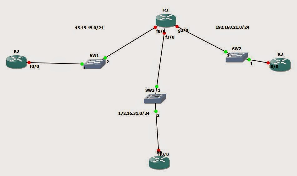
So what I’ve got set up here is a single router with three networks running off it.  In each network I have a single virtual machine configured in Virtualbox (which plays very nicely with GNS3, although this is equally possible with VMWare with just a little more configuration).  The 192.168.21.0/24 network will simulate the internal network.  The 172.16.31.0/24 network will simulate a DMZ network and the 45.45.45.0/24 network will simulate the Internet.

The first thing I’ll set up is basic routing so that all hosts can talk to each other with no access-lists and no address translation.  The router will use the .1 address for each network and the host will use the .20 address.

R1#show ip int br
Interface                  IP-Address      OK? Method Status                Protocol
FastEthernet0/0            45.45.45.1      YES manual up                    up
FastEthernet0/1            unassigned      YES unset  administratively down down
FastEthernet1/0            172.16.31.1     YES manual up                    up
FastEthernet1/1            unassigned      YES unset  administratively down down
GigabitEthernet2/0         192.168.21.1    YES manual up                    up


Now that we’ve got all the networks talking to each other, let’s look at some of the things we may want to block:

•    IP address spoofing – we need to verify that all traffic entering an interface is not from a network attached to another network.
•    TCP SYN-flood attacks – we can use features such as TCP intercept to stop this attack.
•    Information gathering – controlling protocols such as ICMP will stop information about our internal network leaking out to attackers.

We also want to use the concept of least permission, which only grants access to exactly what is required and no more.

I’m not going to run over the ACL information that was covered in CCNA R & S so if you need a refresher the now’s the time to go have a read and understand the basics.

Let’s say now that the first thing we want to do is block any traffic from the Internet.  The easiest way to do this is configure an access-list inbound on interface f0/0 block all traffic with source IP 45.45.45.0 0.0.0.255.

R1(config)#access-list 10 deny 45.45.45.0 0.0.0.255
R1(config)#int fa0/0
R1(config-if)#ip access-group 10 in


That’s it, we’ve configured a standard access list, which only looks at source IP addresses and applied it to int f0/0 inbound.  Let’s give it a test:


We can see now for the PC on the ‘Internet’ that the packets are being filtered whereas earlier they were being allowed.  However this is obviously a poor design, we have a DMZ because we want some services to be available to devices on the Internet.  We’re going to do some more configuration here.
Instead what we can do is apply the same access-list outbound on g2/0.  This will stop the Internet getting to the 192.168.21.0/24 network but allow it to the 172.16.31.0/24 network.
First we’ll remove it from the fa0/0 interface:

R1(config)#int fa0/0
R1(config-if)#no ip access-group 10 in


Now we’ll apply it outbound on g2/0:

R1(config)#int g2/0
R1(config-if)#ip access-group 10 out


Now let’s test this connection:


We can see now that access to the 172.16.31.0 network is working, but access to the 192.168.21.0 network is blocked.  Of course this is still far from ideal, the internet now has full access to our DMZ, we really only want to allow exactly what is necessary and no more.

In order to achieve this we really need to bring in extended access-lists.  Extended access-lists give us the ability to define source ad destination addresses as well as source and destination ports.  I’m also going to introduce the idea of object groups, we can define several objects and put them in a group so we can reference them in a single line in an access-list.

R1(config)#int g2/0
R1(config-if)#no ip access-group 10 out

R1(config)#object-group network InternetServers
R1(config-network-group)#host 45.45.45.20
R1(config-network-group)#host 45.45.45.21

R1(config)#object network DMZ
R1(config-network-group)#172.16.31.0 255.255.255.0
R1(config)#object-group network Internal
R1(config-network-group)#192.168.21.0 255.255.255.0


We’ve defined two servers on the Internet, and also defined our DMZ and internal networks so we can reference them by name in access-lists.
Now let’s come up with a few scenarios that we would like to achieve:
•    Everyone on the internal network can access the Internet for web browsing
•    Everyone on the internal network can access the DMZ but only for management (SSH, HTTPS and RDP)
•    Everyone on the internet can only access the web server (172.16.31.20) but only on HTTP and HTTPS

First let’s define some more object groups – we can define groups of services as well networks and hosts

R1(config)#object-group service MGMT
R1(config-service-group)#tcp 22
R1(config-service-group)#tcp 443
R1(config-service-group)#tcp 3389


R1(config)#object-group service WEB
R1(config-service-group)#tcp 80
R1(config-service-group)#tcp 443


Now let’s define our access-lists, for the three scenarios we are going to need three ACLs:
First we’ll define our access-list with a name.  Now we want to allow management traffic to the DMZ, and block all other traffic to the DMZ, then allow web traffic to anywhere, but block anything else, and we’ll log everything.

R1(config)#ip access-list extended internal_out
R1(config-ext-nacl)#$ permit object-group MGMT object-group Internal object-group DMZ log
R1(config-ext-nacl)#deny ip object-group Internal object-group DMZ log
R1(config-ext-nacl)#permit object-group WEB object-group Internal any log
R1(config-ext-nacl)#deny ip any any log


That’s ticked off our first two requirements, we just need to lock down access to the web server.
R1(config)#ip access-list extended external_in
R1(config-ext-nacl)#permit object-group WEB any host 172.16.31.20 log
R1(config-ext-nacl)#deny ip any any log


Now all we need to do is apply these access-lists to the correct interfaces:

R1(config)#int fa0/0
R1(config-if)#ip access-group external_in in
R1(config)#int g2/0
R1(config-if)#ip access-group internal_out in


Now let’s try access the DMZ from the internet:

From our host 45.45.45.20, I initiated two requests on port 80, one to 172.16.31.21 and one to 172.16.31.20.  We can see that the request to .21 is blocked, but the request to .20 is permitted.
*Nov 26 15:21:38.979: %SEC-6-IPACCESSLOGP: list external_in denied tcp 45.45.45.20(55631) -> 172.16.31.21(80), 1 packet
*Nov 26 15:22:58.619: %SEC-6-IPACCESSLOGP: list external_in permitted tcp 45.45.45.20(53428) -> 172.16.31.20(80), 1 packet


Let’s try something similar from the internal network:

*Nov 26 15:38:36.959: %SEC-6-IPACCESSLOGP: list internal_out permitted tcp 192.168.21.20(56324) -> 172.16.31.20(22), 1 packet
*Nov 26 15:39:14.643: %SEC-6-IPACCESSLOGP: list internal_out denied tcp 192.168.21.20(52198) -> 172.16.31.20(80), 1 packet
*Nov 26 15:40:10.435: %SEC-6-IPACCESSLOGP: list internal_out permitted tcp 192.168.21.20(45556) -> 45.45.45.20(80), 1 packet
*Nov 26 15:40:37.211: %SEC-6-IPACCESSLOGP: list internal_out denied tcp 192.168.21.20(39670) -> 45.45.45.20(23), 1 packet


The four lines above show us that the router is allowing traffic from the internal to the DMZ on port 22, but blocking port 80, however from the internal to the internet port 80 is allowed and port 23 is blocked.

We can also configure IPv6 access-lists, which differ slightly from IPv4 in configuration.  I’ll just create a dummy list as I haven’t configured my VMs with IPv6.

R1(config)#ipv6 access-list V6ACL
R1(config-ipv6-acl)#deny 3ffe:1900:4545:3:200:f8ff:fe21:67cf/128 any

R1(config)#int f0/1
R1(config-if)#ipv6 traffic-filter V6ACL in


For the most part IPv6 access-lists behave the same as IPv4 with just a few keyword differences.

Next up we’ll move onto firewalls.

AAA on a remote server


Why use a centralised server?


Once we start dealing with a large number of devices – many companies can be well into the hundreds or thousands of devices – we need a way of maintaining an always up to date centralised solution to user access control.  It saves us having to configure each device every time a user is added or removed, and means is much tighter as it can be all too easy to forget to remove an administrator once they’ve left company.  Because this is a blog on Cisco security, we’ll talk about Cisco’s product – ACS.
One of the benefits of ACS is that it can plugin to a Microsoft AD server, so that when a device queries the ACS, it then queries the AD server as to a user’s credentials.  It can also use various other external databases, thus removing the need to maintain multiple copies of a user’s credentials dotted around the network.
ACS can be run on top of a Widows server, be a dedicated appliance bought from Cisco, or be installed in a VMWare environment.
There are two protocols to choose from for communication between devices and the ACS, RADIUS and TACACS+.  Usually authentication and authorisation for CLI access will be performed over TACACS+, whereas RADIUS would be more likely to be used to authorise users who are sending packets over a network device such as through a VPN.  RADIUS is an open IETF standard, whereas TACACS is a Cisco proprietary tool, although it is extremely widely used.  TACACS allows much more granular control and can separate the AAA elements into distinct parts, whereas RADIUS combines many of these functions together.  TACACS uses TCP whereas RADIUS uses UDP.  TACACS also encrypts all packets between the server and end devices whereas RADIUS only encrypts the password.  RADIUS however provides a much more detailed accounting capability than TACACS.

Configuring a router to communicate with a ACS


First let’s configure two routers in GNS3 that can talk to each other, to ensure we can get a response to pings at least.


First we want to make sure we can ping the second router:

R1#ping 10.0.0.2

Type escape sequence to abort.
Sending 5, 100-byte ICMP Echos to 10.0.0.2, timeout is 2 seconds:
!!!!!
Success rate is 100 percent (5/5), round-trip min/avg/max = 36/44/52 ms


Now we configure our basic set up – two lists, one for authentication and one for authorisation, both use tacacs and failback to local if tacacs is unreachable.  Then we define our tacacs server with the key, create a username for local login and add the two lists to the remote login ports.

R1(config)#aaa new-model
R1(config)#aaa authentication login AUTHLIST group tacacs+ local
R1(config)#aaa authorization exec EXECLIST group tacacs+ local

R1(config)#username admin privilege 15 secret cisco
R1(config)#tacacs-server host 10.0.0.2 key tacacskey

R1(config)#line vty 0 4
R1(config-line)#authorization exec EXECLIST
R1(config-line)#login authentication AUTHLIST


Now with everything in place, let’s turn the debugging on and have a look at what happens under the hood.

R1#debug tacacs
TACACS access control debugging is on

Basically what happens below is that we initiate a connection to ourselves, the device attempts a connection to the ACS server and when that fails (you can see the 5 sec timeout), it moves onto the local database, which is why we were able to log in successfully.  You could also use the ‘debug aaa authentication’ and ‘debug aaa authorization’ commands.

R1#telnet 10.0.0.1
Trying 10.0.0.1 ... Open


User Access Verification

Username:
*Nov 25 14:28:42.279: TPLUS: Queuing AAA Authentication request 13 for processing
*Nov 25 14:28:42.283: TPLUS: processing authentication start request id 13
*Nov 25 14:28:42.283: TPLUS: Authentication start packet created for 13()
*Nov 25 14:28:42.283: TPLUS: Using server 10.0.0.2
*Nov 25 14:28:42.291: TPLUS(0000000D)/0/NB_WAIT/684303B0: Started 5 sec timeout
*Nov 25 14:28:42.311: TPLUS(0000000D)/0/NB_WAIT: socket event 2
*Nov 25 14:28:42.311: TPLUS(0000000D)/0/NB_WAIT: write to 10.0.0.2 failed with errno 257((ENOTCONN))
*Nov 25 14:28:42.315: TPLUS: Authentication start packet created for 13()
*Nov 25 14:28:42.319: TPLUS(0000000D)/0/684303B0: Processing the reply packet
Username: admin
Password:

R1#
*Nov 25 14:28:51.731: TPLUS: Queuing AAA Authorization request 13 for processing
*Nov 25 14:28:51.735: TPLUS: processing authorization request id 13
*Nov 25 14:28:51.735: TPLUS: Protocol set to None .....Skipping
*Nov 25 14:28:51.739: TPLUS: Sending AV service=shell
*Nov 25 14:28:51.739: TPLUS: Sending AV cmd*
*Nov 25 14:28:51.739: TPLUS: Authorization request created for 13(admin)
*Nov 25 14:28:51.739: TPLUS: using previously set server 10.0.0.2 from group tacacs+
*Nov 25 14:28:51.747: TPLUS(0000000D)/0/NB_WAIT/68430BA8: Started 5 sec timeout
*Nov 25 14:28:51.815: TPLUS(0000000D)/0/NB_WAIT: socket event 2
*Nov 25 14:28:51.815: TPLUS(0000000D)/0/NB_WAIT: write to 10.0.0.2 failed with errno 257((ENOTCONN))
*Nov 25 14:28:51.819: TPLUS: Protocol set to None .....Skipping
*Nov 25 14:28:51.819: TPLUS: Sending AV service=shell
*Nov 25 14:28:51.823: TPLUS: Sending AV cmd*
*Nov 25 14:28:51.823: TPLUS: Authorization request created for 13(admin)
*Nov 25 14:28:51.823: TPLUS: Choosing next server 10.0.0.2
*Nov 25 14:28:51.831: TPLUS(0000000D)/1/NB_WAIT/68430BA8: Started 5 sec timeout
*Nov 25 14:28:51.835: TPLUS(0000000D)/68430BA8: releasing old socket 0
*Nov 25 14:28:51.919: TPLUS(0000000D)/1/NB_WAIT: socket event 2
*Nov 25 14:28:51.919: TPLUS(0000000D)/1/NB_WAIT: write to 10.0.0.2 failed with errno 257((ENOTCONN))
*Nov 25 14:28:51.919: TPLUS: Protocol set to None .....Skipping
*Nov 25 14:28:51.923: TPLUS: Sending AV service=shell
*Nov 25 14:28:51.923: TPLUS: Sending AV cmd*
*Nov 25 14:28:51.923: TPLUS: Authorization request created for 13(admin)
*Nov 25 14:28:51.927: TPLUS: Choosing next server 10.0.0.2
*Nov 25 14:28:51.935: TPLUS(0000000D)/0/NB_WAIT/68430BA8: Started 5 sec timeout
*Nov 25 14:28:51.935: TPLUS(0000000D)/68430BA8: releasing old socket 1
*Nov 25 14:28:52.047: TPLUS(0000000D)/0/NB_WAIT: socket event 2
*Nov 25 14:28:52.047: TPLUS(0000000D)/0/NB_WAIT: write to 10.0.0.2 failed with errno 257((ENOTCONN))
*Nov 25 14:28:52.051: TPLUS: Protocol set to None .....Skipping
*Nov 25 14:28:52.051: TPLUS: Sending AV service=shell
*Nov 25 14:28:52.051: TPLUS: Sending AV cmd*
*Nov 25 14:28:52.055: TPLUS: Authorization request created for 13(admin)
*Nov 25 14:28:52.055: TPLUS(0000000D)/0/68430BA8: Processing the reply packet


IPv6


Why is there a need to move to IPv6?  Simply because we are running out of public IPv4 addresses.  IPv4 uses 32 bits to represent an IP address and thus can support 4,294,97,296 addresses, or approximately one public address for every 2 people on earth.  With the connected world we live in now, this is clearly not enough, even with NAT to lump a pile of private IP addresses into single public addresses.
IPv6 uses 128 bits to represent addresses, and thus can support about 42 octillion addresses per person.  Because of this complete overabundance in addressing, there is no NAT in IPv6 at all; all addresses are considered public addresses.  Hosts are able to assign addresses to themselves; however addresses can also be assigned similarly DHCP.  There is a wealth of information online about the differences between IPv4 and IPv6, they are well worth a read, eventually we will all be making the move to IPv6.

Potential Risks with IPv6


•    Network Discovery Protocol – A rogue router could send incorrect information to clients, leading to a potential man in the middle attack.
•    DHCPv6 – Similar to above, a rogue router could send incorrect DHCP information to a client
•    Hop-by-hop extension headers – with IPv6 it is possible in the header of a packet to specify the intermediary hops to take in the path to the destination, so it’s possible for a rogue router to dictate the path and redirect through a man in the middle attack.
•    Packet amplification attacks – using multicast addressing it is possible to trick entire networks into responding to requests.
•    ICMPv6
•    Tunnelling – Tunnelling IPv6 through IPv4 may mean some IPv4 filtering in the network may work incorrectly.
•    Autoconfiguration – Rogue routers can cause end devices to autoconfigure themselves incorrectly.
•    Dual stacks – A device can become compromised if it is running IPv4 and IPv6 simultaneously but one more frequently than the other.

IPv6 Best Practices


•    Filter bogus addresses
•    Filter non-local multicast addresses
•    Filter ICMPv traffic that is not required
•    Drop routing header type 0 – stop hop-by-hop extension headers.
•    Use manual tunnels
•    Protect against rogue devices – Secure Neighbor Discovery (SEND) and router advertisement guard (RA guard) can help to stop rogue devices.

Tuesday 25 November 2014

Finishing securing the Management Plane


Troubleshooting


What we’ll do now is create a fresh router configuration to do some troubleshooting, so if you’re following along, then start again from scratch.

First we’ll assign an IP address to the router so we can connect to it.
R1(config)#interface loopback 0

R1(config-if)#ip address 10.0.0.1 255.255.255.0


Create a user with privilege level 15
R1(config)#username admin privilege 15 secret password

Enable aaa and create authentication, and authorisation lists.

The exec authorisation list will create an exec shell and place the user in in their privilege level automatically.  The commands list will require authorisation for every level 15 command issued.
R1(config)#aaa new-model
R1(config)#aaa authentication login LOCALAUTH local
R1(config)#aaa authorization exec EXECPROMPT local
R1(config)#aaa authorization commands 15 PRIV15COMM local

Apply the lists to the telnet port
R1(config)#line vty 0 4
R1(config-line)#login authentication LOCALAUTH
R1(config-line)#authorization exec EXECPROMPT
R1(config-line)#authorization commands 15 PRIV15COMM
R1(config-line)#exit

Issue the debug commands so that we can see the output when we try to connect.
R1#debug aaa authentication
R1#debug aaa authorization


R1#telnet 10.0.0.1
Trying 10.0.0.1 ... Open


User Access Verification

Username: admin
*Nov 24 16:10:57.615: AAA/BIND(0000000D): Bind i/f
*Nov 24 16:10:57.623: AAA/AUTHEN/LOGIN (0000000D): Pick method list 'LOCALAUTH'
Password:

R1#
*Nov 24 16:11:05.963: AAA/AUTHOR (0xD): Pick method list 'EXECPROMPT'
*Nov 24 16:11:05.971: AAA/AUTHOR/EXEC(0000000D): processing AV cmd=
*Nov 24 16:11:05.975: AAA/AUTHOR/EXEC(0000000D): processing AV priv-lvl=15
*Nov 24 16:11:05.975: AAA/AUTHOR/EXEC(0000000D): Authorization successful

Above we can see that it picks the list ‘LOCALAUTH’ to authenticate the users which is the list we specified earlier.  We can also see it picking the ‘EXECPROMPT’ list.


R1#conf t
Enter configuration commands, one per line.  End with CNTL/Z.
R1(config)#
*Nov 24 16:11:36.291: AAA/AUTHOR: auth_need : user= 'admin' ruser= 'R1'rem_addr= '10.0.0.1' priv= 15 list= 'PRIV15COMM' AUTHOR-TYPE= 'command'
*Nov 24 16:11:36.295: AAA: parse name=tty2 idb type=-1 tty=-1
*Nov 24 16:11:36.295: AAA: name=tty2 flags=0x11 type=5 shelf=0 slot=0 adapter=0 port=2 channel=0
*Nov 24 16:11:36.295: AAA/MEMORY: create_user (0x68733894) user='admin' ruser='R1' ds0=0 port='tty2' rem_addr='10.0.0.1' authen_type=ASCII service=NONE priv=15 initial_task_id='0', vrf= (id=0)
*Nov 24 16:11:36.299: tty2 AAA/AUTHOR/CMD (3587652350): Port='tty2' list='PRIV15COMM' service=CMD
*Nov 24 16:11:36.299: AAA/AUTHOR/CMD: tty2 (3587652350) user='admin'
*Nov 24 16:11:36.299: tty2 AAA/AUTHOR/CMD (3587652350): send AV service=shell
*Nov 24 16:11:36.299: tty2 AAA/AUTHOR/CMD (3587652350): send AV cmd=configure
*Nov 24 16:11:36.299: tty2 AAA/AUTHOR/CMD (3587652350): send AV cmd-arg=terminal
*Nov 24 16:11:36.303: tty2 AAA/AUTHOR/CMD (3587652350): send AV cmd-arg=<cr>
*Nov 24 16:11:36.303: tty2 AAA/AUTHOR/CMD(3587652350): found list "PRIV15COMM"
*Nov 24 16:11:36.303: tty2 AAA/AUTHOR/CMD (3587652350): Method=LOCAL
*Nov 24 16:11:36.303: AAA/AUTHOR (3587652350): Post authorization status = PASS_ADD
*Nov 24 16:11:36.303: AAA/MEMORY: free_user (0x68733894) user='admin' ruser='R1' port='tty2' rem_addr='10.0.0.1' authen_type=ASCII service=NONE priv=15 vrf= (id=0)

When we issue the ‘conf t’ command, the debug log shows a reference to the "PRIV15COMM" list.


Role-based access configuration


What we are doing here is assigning commands to a custom privilege level, in this case privilege level 10.  If a user connects at privilege level 10, they will now be able to issue the ‘configure terminal’ command.  We are also issuing a new enable password specifically for privilege level 10.

R1(config)#privilege exec level 10 configure terminal
R1(config)#enable secret level 10 0 newpassword


R1>show privilege
Current privilege level is 1

R1>enable ?
  <0-15>  Enable level
  view    Set into the existing view
  <cr>

Log in as privilege 10, enter configuration mode, and with the ‘?’ you can see what commands are available to you.  Because we haven’t configured any custom commands apart from the configure terminal, this is the default for level 10.

R1>enable 10
Password:

R1#conf t
R1(config)#?
Configure commands:
  beep     Configure BEEP (Blocks Extensible Exchange Protocol)
  call     Configure Call parameters
  default  Set a command to its defaults
  end      Exit from configure mode
  exit     Exit from configure mode
  help     Description of the interactive help system
  netconf  Configure NETCONF
  no       Negate a command or set its defaults
  oer      Optimized Exit Routing configuration submodes
  sasl     Configure SASL
  wsma     Configure Web Services Management Agents

Custom views


Begin the view creating process, using the enable secret configured earlier.

R1#enable view
Password:

Create a view called ‘TESTVIEW’, assign it a secret, and assign the commands available to that view.  In this case we are allowing all show commands, plus ping and traceroute, this might be a view you use for first line troubleshooting to allow them to investigate incidents but not allowing any configuration changes.

R1(config)#parser view TESTVIEW
R1(config-view)#secret testviewpassword
R1(config-view)#commands exec include ping
R1(config-view)#commands exec include all show
R1(config-view)#commands exec include traceroute

R1#enable view TESTVIEW
Password:

Switch to the new view and by issuing the ‘?’ command we can see what is available to us.

R1#show parser view
Current view is 'TESTVIEW'

R1#?
Exec commands:
  enable      Turn on privileged commands
  exit        Exit from the EXEC
  ping        Send echo messages
  show        Show running system information
  traceroute  Trace route to destination

Lastly, we can assign views to users, so when the use logs in they are automatically put into this view, with the associated commands available to them.

R1(config)#username TEST view TESTVIEW secret cisco


SSH and HTTPS


We’re going to start with a fresh config again, so issue the ‘write erase’ command if you’ve been applying the configuration so far.

In order to allow connectivity by SSH we have to generate a public/private key pair.
As we can see with these commands, first we need to define a custom hostname, and a custom domain name.

Router(config)#crypto key generate rsa
% Please define a hostname other than Router.
Router(config)#hostname TestRouter
TestRouter(config)#crypto key generate rsa
% Please define a domain-name first.
TestRouter(config)#ip domain-name test.com
TestRouter(config)#crypto key generate rsa
The name for the keys will be: TestRouter.test.com
Choose the size of the key modulus in the range of 360 to 2048 for your
  General Purpose Keys. Choosing a key modulus greater than 512 may take
  a few minutes.

How many bits in the modulus [512]: 1024
% Generating 1024 bit RSA keys, keys will be non-exportable...[OK]

TestRouter(config)#username test secret testpassword

TestRouter(config)#aaa new-model
TestRouter(config)#aaa authentication login TESTLIST local
TestRouter(config)#line vty 0 4
TestRouter(config-line)#login authentication TESTLIST

TestRouter(config)#int loopback 0
TestRouter(config-if)#ip address
*Nov 25 10:13:52.159: %LINEPROTO-5-UPDOWN: Line protocol on Interface Loopback0, changed state to up
TestRouter(config-if)#ip address 10.0.0.1 255.255.255.0

We can now use our test account to verify that we can SSH to the router.

TestRouter#ssh -l test 10.0.0.1

Password:


TestRouter>show ssh
Connection      Version Encryption      State                   Username
0               1.5     3DES            Session started         test
%No SSHv2 server connections running.
TestRouter>

We need to do a little more configuration to enable the https server on the device


TestRouter(config)#ip http secure-server

% Generating 1024 bit RSA keys, keys will be non-exportable...[OK]

TestRouter(config)#

*Nov 25 11:19:45.691: %PKI-4-NOAUTOSAVE: Configuration was modified.  Issue "write memory" to save new certificate
TestRouter(config)#ip http authentication local
TestRouter#wr mem


Logging


Logging is incredibly important for troubleshooting so we will run through some basic logging tasks.
First we can see that currently there is no time associated with the current logging details, so let’s fix that.

TestRouter(config)#int fa 0/0
TestRouter(config-if)#no shut
TestRouter(config-if)#
%LINK-3-UPDOWN: Interface FastEthernet0/0, changed state to up
%LINEPROTO-5-UPDOWN: Line protocol on Interface FastEthernet0/0, changed state to up

TestRouter(config)#service timestamps log datetime
TestRouter(config)#int fa0/0
TestRouter(config-if)#shut
TestRouter(config-if)#
*Nov 25 11:24:39: %LINK-5-CHANGED: Interface FastEthernet0/0, changed state to administratively down
*Nov 25 11:24:40: %LINEPROTO-5-UPDOWN: Line protocol on Interface FastEthernet0/0, changed state to down

We also can configure logging to a syslog server, and logging to the buffer.  We ca configure custom logging levels to include as well, note that any logging level we choose will also include any messages at a higher importance.  So if we set logging to debugging, it will include all events, but if we set it to informational, then it will include all higher, but will exclude debugging messages.

First point the logging to a configured syslog server, and set the level to debugging.
TestRouter(config)#logging 192.168.0.1
TestRouter(config)#logging trap debugging

We can also output logs to the buffer, and configure the size of the buffer at the same time.  Due to the size of the buffer we will only include more important messages:
TestRouter(config)#logging buffered 8192 errors

SNMP


Simple Network Management Protocol (SNMP) is the protocol which we use to manage network nodes; it is most often used as a way of centralising information about all our network devices and providing overview of issues that may have occurred in the network.

SNMP consists of 3 components:
·         SNMP manager – Sometimes called a Network Management Server (NMS)
·         SNMP agent – software which runs on the network device
·         Management Information Base (MIB) – defined by a series of objects, which is defined by the MIB.  A collection of unique numbers associated with each of the individual components of the device.

There are also 3 main varieties of SNMP messages:
·         GET – used to retrieve information from a device
·         SET – used to set a variable in a device
·         Trap – a message from a device to the manager about an event.

SNMP can pose a major security to our network, particularly if we use SNMPv or v2c.  If an attacker were able to get a rogue NMS onto our network, not only could they gain information about all the devices in our network, using SET messages they could potentially alter our device configuration.  Versions 1 and 2c of SNMP both use the concept of community strings to verify access to a device, essentially passwords; however these weaknesses have been addressed in version 3.

SNMP version 3 introduces the concept of security levels:
·         noAuthNoPriv – no authentication of devices and no encryption of traffic.
·         authNoPriv – authenticate devices using HMAC with MD5 or SHA, no encryption
·         authPriv – authenticate as above, and provide encryption of traffic using CBC-DES (DES-56)

This allows us to ensure integrity, authentication and encryption in version 3.

Configuration is relatively simple:

Set the server location, contact, community string and the host:

TestRouter(config)#snmp-server location 10.0.0.25
TestRouter(config)#snmp-server contact Test User
TestRouter(config)#snmp-server community super-secret TEST
TestRouter(config)#snmp-server host 10.0.0.25 traps STRING


NTP


NTP version 3 also supports authentication to ensure we are not getting an incorrect time from a rogue NTP server.

TestRouter(config)#ntp update-calendar
TestRouter(config)#ntp authentication-key 1 md5 AUTHKEY
TestRouter(config)#ntp authenticate
TestRouter(config)#ntp trusted-key 1
TestRouter(config)#ntp server 10.0.0.27 key 1 source FastEthernet 0/0 prefer


Securing configuration files


To secure the boot image and configuration files we just need to issue two commands.  These commands ensure that the boot image and configuration files cannot be deleted by a remote user:

The secure boot-image will fail in GNS3 but the secure boot-config will work.
TestRouter(config)#secure boot-image
TestRouter(config)#secure boot-config
TestRouter(config)#
*Nov 25 12:21:00: %IOS_RESILIENCE-5-CONFIG_RESIL_ACTIVE: Successfully secured config archive [disk0:.runcfg-20141125-122059.ar]


Well that was a long couple of blog posts, next up we’ll be looking at getting AAA running on IOS with an ACS server.